Controller Wiring

updated May  2023 


Plunger Controllers

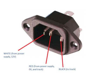
A plunger controller should be wired to a plug as follows-

NOTE this diagram is for a modern plunger controller - the  long obsolete  "barrel" controllers from MRRC , VIP or  Tradeship  must be wired differently see separate diagram .

The diagram on the left shows how to wire a resistance controller to BSCRA rules. The plug from on top. The plugs almost invariably have N E and L molded in if you look closely.  On the left is the standard for track wiring.  The controller should always be wired the same way with the  positive (+) side of the power supply going to the controller, and the negative (-) side going direct to the track and brake terminal.

The wire colours shown are conventional plug wiring. Unfortunately not all controller makers follow the same wire colour standard.  The important thing is the right pin goes to the correct part of the controller. MRRC controllers always used to have green to N;  red to E ; and black to L.   The German ADC controllers use red for full power/ power supply +: black is brake / power supply: yellow is the track/ wiper. 

For controllers with no brake connection only have two wires, these are connected to the N and L pin, see the section on resistance controllers for more detail.


NOTE - This diagrams omits switches, fuses etc.  Click here for the full instructions on track wiring.

Trigger controllers

Trigger controllers should be wired to a plug as follows.

The wire colours shown are the international standard used on most controllers suitable for ISRA / BSCRA racing, including  Parma controllers.  Generally US made controllers come with Croc clips or 4mm banana plugs in the colours shown below.   This is because their tracks have 3 separate studs, or 3 separate studs for controller connection rather than the normal British 3 pin plug. When I say British, this is the BSCRA standard, but most non- BSCRA clubs also follow this standard.   

ISRA Tracks

In 2016 ISRA introduced a 3 pin IEC 60320 connector standard in addition to the traditional separate red-white-black 4mm banana sockets  It is to be expected these will be increasingly adopted on tracks used for international racing.
The controller uses a C 13  free female connector and the track has a C 14 fixed male connector wired as shown below

isra_socket.jpg


Scalextric Sport and Ninco resistance controllers are connected to the track with a jack plug.  These are connected as shown . The cable end contact is connected to the power band (L on a BSCRA style plug). The center contact is  connected to the the controller wiper (N on a BSCRA style plug). The end contact is  connected to the the controller brake band  (E on a BSCRA style plug).  Policar use the same size jack plug but it is NOT wired the same way, brake and power are swapped over in this brand.  Policar controllers use green wire for brake,  red wire for power and black for wiper : The controllers polarity is  NOT wired the same way as the BSCRA standard on most home sets. this isn't a problem with resistance controllers but most electronic controller won't work with tracks wired to a different controller polarity.


XLR Connectors  - some tracks use 3 pin  XLR connectors for controller hook up.   I've not seen these myself, but it's reported that there are (at least) three conflicting standards
Clubs in the North Western USA and clubs in France use  Track/Wiper (Black) to pin 1 : Full Power (White) to pin 2 : Brake (Red) to  pin 3.
Avant Controllers Full Power (White) to pin 1 : Brake (Red) to  pin 2. : Track (Black) to pin 3
The standard used in New Zealand and supplied to some Australian clubs has a different pin out (to be confirmed what it is)
In the absence of a universal standard, I'd recommend checking with the club / raceway to make sure you are hooked up correctly for the way their XLR sockets are wired.


Chokes

A choke (in slot racing jargon) is a device for reducing power to the car.    The diagram below shows an example of  where to connect an external choke.   

Brake Boxes

Adjustable braking reduces the car's breaking from the full dynamic braking provided by the controller's brake contacts.   They can be built into the controller or housed in a separate external box,  Often  the brake adjustment uses a  2 or 3 ohms adjustable resistor to give a  resistance from a fraction of an ohm up to 2 or 3 ohms. For low power cars (such as would be driven with a 25 or 45 ohms controller) a 25 ohm adjustable resistor would be more suitable.  The diagram below shows an example of  where an external brake box is connected.   

"Barrel" type controllers
"Barrel" controllers from MRRC , VIP or  Tradeship  are  wired as shown below .   This wiring only applies to "Barrel" type controllers, for more Modern plunger controllers see the diagram above.  The photos below are of a Tradeship "Barrel" controller, but the other makes look very similar.

Tradeship barrel      Tradeship barrel  parts

Tradeship barrel      Tradeship barrel  parts


Copyright © 2000, 2001, 2004, 2009, 2010, 2013 -2023 C.Frost All rights reserved

 No liability is accepted for the information on this site or any use to which it may be put