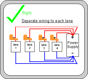
How much power is available to a car depends on the track
power supply and the track wiring. For a motor to
perform to it's full potential you need both - a power supply producing at least
enough current (amps) at a suitable voltage AND wiring so that voltage doesn't
drop too much between the power supply and the car. If the power
supply can deliver enough power for a motor to perform to its full potential on
a short track, it will deliver enough power for a long track. A
longer track will need more/ thicker track wiring than a short one. There
is a common misconception that longer tracks need a more powerful power supply
than short tracks - it doesn't! The power supply only needs upgrading if
higher current motors are being used, or of course if the power supply was
inadequate in the first place.
Let's at wiring and power supplies in more detail : -
Wiring
There are two ways I could cover track
wiring - either give a detailed explanation of why a particular size of wire is needed,
or just give a simple guide to what to do. No doubt some readers will
just want the simple approach, and others will want the reasons, facts figures,
graphs etc. I aim to provide answers for both sort of reader - read on for
the what to do guide - the reasons, facts figures,
graphs etc are in the next article in this series.
The Simple What To Do Guide
For those who donít want to
mess around with the reasons why things work here are a few quick guide-lines on
track wiring that should provide a reasonable amount of power. It assumes
a normal club size track, running BSCRA type cars. For lower powered cars the
principles are identical, but lower thinner wiring will suffice. A lot of clubs now use
electronic power supplies in place of batteries - these rules apply equally well
to both (but I won't keep repeating "battery or power supply").
1) Use separate feed wires from
the negative power supplyterminal for each lane. Although a SHORT length
(less than a metre) of VERY THICK wire from the battery to the point
where the wires separate is tolerable the general rule is DO NOT USE COMMON
RETURN WIRING.
2) Obviously the positive wiring
has to separate fairly near the battery to go to the separate controller sockets. Ideally use separate feed wires from
the positive battery terminal for each socket. Although a SHORT length
(less than a metre) of VERY THICK wire from the battery to the point
where the wires separate is tolerable.
3) Keep the wiring from the
battery to the controller sockets as short as possible.
4) Keep the wiring from the
controller sockets to the track as short as possible.
5) Keep any wiring from the power
supply to the track as short as possible.
NOTE For tracks where the drivers
rostrum is next to the track (like most tracks) 3,4 & 5 can be achieved by
putting the power supply under the track close to the middle of the rostrum.
6) I would recommend at least 5
power feeds for a 30m / 100ft lap length TAPE track. (4 might be adequate
for a very compact layout.) More feeds are needed where the lap length is longer
( as a rule of thumb, one feed per extra 6m/20 ft. of lap length).
7) For braided tracks a
single power feed may well be adequate for tracks up to around 30m / 100ft lap
length a second feed will be needed where the lap length is longer.
8) Run the first set of extra
feed wires run from from the main power feed to a convenient point about half
way round the lap length. Its important to keep these wires short, so for
example if the feed wires can be 5m shorter if they connect 5m from half way
round, then go for the shorter wire. The extra feeds should be distributed
evenly round the lap length.
9) Separate feed wires are needed
for the positive and negative side of each lane.
10) Use 2.5sq.mm cable (ring main
cable or similar) for track wiring (including extra power feeds) (but something
much thicker is needed where VERY THICK wire is recommended)
11) Connect up the tape / braid
as a continuous loop round the track - a break in the connection increases the
resistance considerably.
Which Wire Goes Where?
Making cars run forwards without blowing controllers!
The current BSCRA standard has the cars wired so that when looking down on the car in the direction of travel the
positive braid is on the right. Most imported American ready to run
cars, standard home set cars (Scalextric,
Fly, Ninco etc.) are also wired to go forward when the positive braid is on the
right.
(The original Association standards
since they were first published in 1961 was positive on the left. BSCRA will be changed over to the "plus on the right" standard
on 1 Jan 2003. )
At first you might think
that the wiring options shown in either of the left
hand parts of Diagram T would make BSCRA 2003 and "Scalex etc." cars go forward. Well
if you use a resistance controller either will work. If you try to use a
transistorised controller, the wiring with the big green tick will work fine and
your car will go forward. However the wiring on the
lower part of Diagram T will blow up your transistorised controller and none of
your cars will go anywhere (even on a correctly wired track) until your
controller is repaired (Probably with a new transistor). On the right hand
side are the equivalent diagrams to make the cars go backward ( which is
only rarely used).
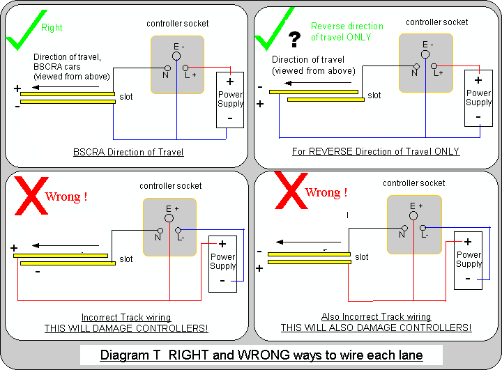
Why does it make any difference to your controller which
way the track is wired? Looking at the controller socket the standard wiring
(Top of Diagram T) has the E terminal (the brake) wired negative and the L
terminal (the power connection) wired positive. Transistorised controllers are
designed to work this way round. Looking at the lower half of Diagram T, youíll
notice the E terminal (the brake) wired positive and the L terminal (the power
connection) wired negative. This
connects the transistors back to front, so they will not work, and unless you
are very lucky they are destroyed (this happens far quicker than you can unplug
the controller, and faster than a fuse can blow.) Unfortunately there is no
simple change that can be made to a controller to get round this problem - the
only simple solutions are to wire the track properly or use a resistance
controller. (unlike transistors, resistors work exactly the same whichever way
the current is passing through them.)
Using the track in the opposite direction
Do you always want to run the track in one
direction? Running in the opposite direction gives
effectively a different circuit to race on - some layouts work well in either
direction. It's sometimes more difficult to drive a track in one direction than
the other - bends that open up are often easier to drive than ones that tighten
(the Oaklands Park circuit is a good example of this) There are potential
problems with running backward. Cars will deslot in different places in
the reverse direction so the
marshalling positions will often be significantly different, and there can be a
higher risk of cars landing in awkward places (like under the bridge). Some of
the imperfections in track
building upset cars much more in one direction than the other.
If you want to run either type of car without
having to rewire each car, or you want the option of running either way round
the track without swapping over the wires on the car - the track needs to be wired to allow either. Many
clubs now run both types of car, unless you are quite sure the track will only
be used for one type, I recommend the track is wired top allow both types of
car. It might
appear easiest just to connect the battery / power supply the other way round -
unfortunately this produces incorrect controller connections (as the lower half of Diagram
T). The right way to do it is to swap over the connections to the lane on the
track side of the controller socket as shown in Diagram U. (Cars wired to 2003
standard will run in the reverse direction with the switch in the 2002 position.
Cars wired to 2002 standard will run in the reverse direction with the switch in
the 2003 position.)
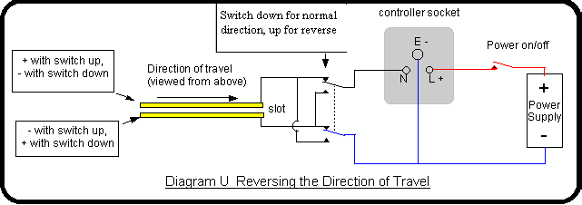
Iíve shown a two pole switch, it will
also work with relay(s) or plug/sockets. These are carrying the full power to
the cars so
(a) The switches, relays, plugs/sockets need to
be of a suitably high current rating (20 amp. for strap cars)
(b) The power wiring must not be extended any
more than absolutely necessary or else there will be voltage drops in the
wiring.
This means the switches, relays, plugs/sockets
will almost certainly need to be under the track. If you envisage frequent
changes between the wiring polarity, its convenient to use relays and have the
switches at race control. (Switches on the drivers rostrum are an option - this
makes it easier for the sensible drivers - but gives more opportunities to the
less sensible for messing about.)
IF the track polarity is reversible, the lap
counters will also need to be suitable for running in both directions - this is
covered in the Lap Counter article.
Turning
the power on and off
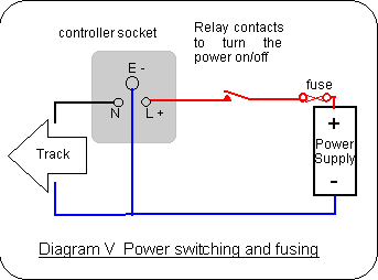
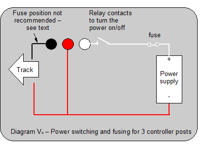
Diagrams V and Va
show connections for
sockets used in BSCRA racing and the 3 controller post set up used
on a lot of other countries. The "power on/off" shown in Diagram V
and Va
would
usually be a relay contact. This should be mounted between the power supply and
the socket as shown. This removes power from the controller
when track power is turned off which can be very useful if a faulty controller
is plugged in. (Putting the power on/off on the "N" lead (the black
wire in Diagram V) would still turn off the track but would leave the power
permanently connected to the controller)
The power relay should have
contacts rated to carry the maximum current a car will take. 20 amps per lane is
adequate for BSCRA cars. A separate contact for each lane is ideal. A separate
relay for each lane is a good idea - it allows individual lanes to be switched
off which can be useful in holding cars on the start line. These relays are
available for a few pounds each, and are commonly used in full size cars.
This will work well for home set type cars, but if higher power cars are never
going to be used a much lower rating relay is adequate.
Protection
against faults
The fuse shown in Diagrams
V and Va
protects the track
wiring and minimizes damage to controllers in the event of a faulty (or
incorrectly wired) controller or other dead short circuits. Domestic 15amp
fusewire (0.5mm) or a 25 amp plug in automotive type fuse is suitable for this fuse - practical experience is that this
does not blow in normal use - even with 25g armatures - even with the sort of
short circuit exhibited by a chassis sparking on the tapes as it goes round (yes
I hope that's not normal use)- but it does blow instantly when somebody plugs in
a controller with the E and L terminal are shorted through the brakes. Just in
case you were wondering - a couple of cm. of 15 amp. fuse wire has negligible
resistance compared with the rest of the track wiring, so it will not slow the
cars down. You might be surprised that experience shows the
rating for fusewire is so different to automotive type fuses, it's
probably got something to do with how fast they blow on overload but I
haven't investigated the reasons in depth.
A fuse in the black wire is sometimes suggested, see Diagram
Va.
This provided the same protection against
track short circuits as the fuse shown next to the power supply +
connection, However a fuse in the black wire does not give any
protection against some of the common controller faults so it is NOT
recommended.
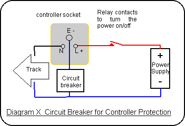
Some American tracks use a 10
amp. circuit breaker wired into the brake connection (see Diagram X). This
provides similar protection for incorrectly wired controllers, but doesnít
protect against other short circuits. It's also likely to have a small resistance
which may slightly reduce the brakes. Incorrectly wired controllers are a
more likely problem - particularly as many American tracks depend on
separate croc clips for each wire rather than a 3 pin connector. (With separate
stud connections, the careless competitor has the opportunity to wire up his
controller wrongly every time he plugs into the track. With a 3 pin connector
once the plug is wired up right you cannot go wrong.)
The standard wiring for the studs
on American tracks is
L pin - To Battery Positive -
White Stud
E pin - To Battery Negative - Red
Stud
N pin - Power to car - Black Stud
Is
there a Constant Voltage all round the Track?
It would suit slot cars very well
if the voltage arriving at the motor was always the same whenever you put your
thumb hard down. So why isnít that just what you get on any slot track?
There is a popular misconception
that copper wire has no resistance - this is not true - the first thing to
understand is that copper wiring has resistance and that resistance is enough to
reduce the voltage to your car by a very noticeable amount. There is also a
misconception that car batteries produce a constant voltage under varying loads
- this is not true either - the voltage drops with increasing load. Generally, electronic
power supplies provide a more constant voltage than a battery. The
combination of these voltage drops is the reason the lights on your full size
car go dim when you turn over the starter motor.
In fact it doesnít matter much if the power available is
exactly equal all the way round the track (Good job too because there's no
practical way of making it exactly equal all the way round as Iíll explain
later). Certainly adequate power is needed all the way round, but less power is
"adequate" in a bend where you cannot put your controller full down
than on a straight where cars are accelerating on full power. As long as the
power available on any particular part of the track is the same every lap, it
just becomes part of learning the track .... Drivers learn to deal with the
different levels of power just as they learn to deal with different radii bends
on different parts of the track. The voltage from some club batteries go down
slowly by half a volt during a 3 min race, and the drivers naturally compensate
(by braking a little later and applying a bit more throttle in corners) without
realising they were doing it. What drivers cannot compensate for is power going
up and down by the split second depending on how much power the other cars are taking.
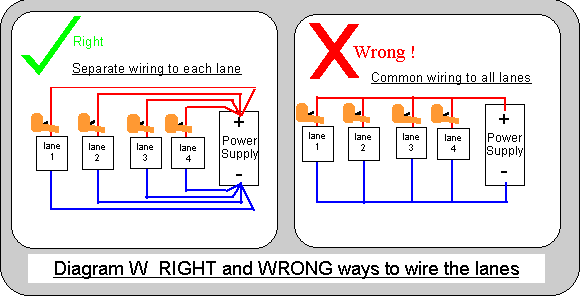
Separate wiring to each lane is important. If the wiring
is common (see "wrong!" half of Diagram W), when one lane is drawing
power the voltage to all the lanes will drop by say 1 volt. So the
power to all the lanes will go up by 1 volt when one car brakes, and the power
on all the lanes goes down again when the driver on one lane puts his thumb
down. With separate wiring each lane has the same voltage available regardless
of what the other lanes are doing! (see left hand half of Diagram W)
The maximum power available to the car is limited
by -
(1) how much power is lost in the resistance
between the car and the battery / power supply.
(2) the power available at the battery / power
supply.
The next article in this series explains what
sort of wire to use, why, and includes some graphs to show what happens
all the way round the track. If you just want a
simple what to do guide go to the top of this page.
Power Supplies
The power for the cars comes from the track power
supply - traditionally this was a car battery with some sort of charger.
These days the use of batteries is quite rare. High current
electronic "regulated" power supplies are available at reasonable cost
and are generally used without a battery. For home set type cars
low cost unregulated power supplies can be used.
A 12 volt car battery is a good source of high
current dc at a fairly constant voltage, and was the standard choice for many
years (although they are now less common). The battery needs to be recharged otherwise it'll go flat fairly
quickly. The voltage from a battery is at best only fairly
constant. The combination of clapped out batteries and poorly regulated
chargers, that used to be all to common, produces disappointingly large
variations in voltage. In fact poorly regulated chargers can quickly
convert a good new battery into a clapped out one!
So what do you need in a battery charger?
(1) A trickle charger will do the battery no harm,
and will recharge it eventually. This means only a few amps of charging
current, and unfortunately means that high powered cars will drain the battery
rather much more quickly than the trickle charger can replace it.
(2) A higher current charger that turns itself off very quickly when full charge
voltage is reached. This is how traditional car charging systems work, and
in the early days of slot racing car parts were the most common way of doing it.
(3) A constant voltage charger set to the correct float charge voltage for the
battery (13.8v is usually recommended for
batteries with lead/antimony plates, 14.2v is usually recommended for batteries
with lead/silicon plates). An electronically regulated supply is usually
used - ideally 10 amps per lane (e.g. 40 amps for a 4 lane track) so you can
deal with any motor, but many clubs manage with considerably less.
So what do you need in a power supply (without
battery)?
You need a power supply that can give each motor the maximum current (amps) it
needs. That means the maximum motor current multiplied by the number of
lanes. Here are some examples
(1) For high power cars 20 amps per lane is needed - a 40 amp supply
shared between two lanes etc. is OK but for championship use a power supply with
35 amps is normally used..
A 75 amp supply shared between 4 lanes seems to work
fine.
(2) For group 12 powered cars 10 amps per lane is needed - so a 40 amp
supply shared between four lanes etc. is OK but for championship more is
normally used..
(3) For Falcon powered cars 8 amps per lane is adequate - so a 40 amp
supply shared between four lanes will do nicely.
(4) For home set type cars 2 amps per lane is enough - so a 4 or 5 amp
supply shared between two lanes etc. will do nicely.
Is a higher current power supply a
acceptable?
YES Motors only take as much current as they need. For example if a
low power motor running at speed needs half an amp then it'll only take
half an amp even if the power supply is capable of supplying 100
amps.
Even for home set use it makes sense to buy a big enough supply to cope with the
highest current motors you are likely to want to run. Cost is a reason
for not going too far above the current you need.
Higher current power supplies will put more current into a fault, so protection
against faults is important.
Does lap length makes a difference to what power
supply is needed? No (except possibly with digital tracks) - BUT extra
wiring is usually needed for extra lap length.
Some electronic power supplies can be connected in parallel satisfactorily,
some cannot. The best way to avoid this problem is to connect
supplies to lanes individually - so for example if you have two 40 amp supplies
for your 4 lane track connect two lanes to one power supply and the other two
lanes to the other power supply as shown in the diagram below.
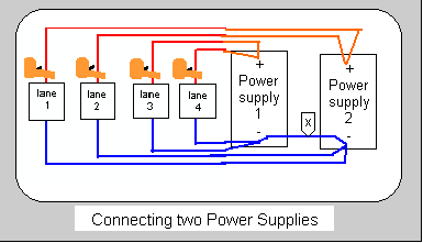
NOTE - The blue wire
"x" in the diagram is often necessary to get the lap recorders working
- the power supply to the cars will work properly if it omitted.
There seem to be plenty of suitable
power supplies about. For example, the BSCRA Nationals track currently
uses four Rapid Electronics 40 amp switch mode power supplies (part number
85-1828) - two lanes from each supply and no batteries. The output voltage
is adjustable, they are used on the fixed 13.8 volt setting for championship
racing, but for charity events lower voltages are used.
Adjustable Voltage Power
supplies with an adjustable voltage are often used on slot tracks. Many
clubs simply want a fixed voltage, and never make use of the voltage adjustment.
Adjustable voltage provides a useful way of reducing power, for example when
opening a track to the public (see section 7).
Capacitors - some tracks
(particularly in North America) use large capacitors connected to the power
supplies. I haven't measured the supply on a track with these fitted so
I'll only offer a theoretical observation. The capacitors will maintain
the the track voltage over very short periods (fractions of a second) of high
current load, which can help with the peak current when starting from rest. They should also be useful for reducing ac ripple (
ac ripple was a problem with simple mains frequency transformer power supplies,
but shouldn't be a problem with switch mode power supplies). There is no
guarantee all power supplies will start up with capacitors connected.
Home
set power supplies
Many home set tracks come with a low cost
unregulated power supply. These are suitable for their intended purpose,
but can present problems for the enthusiast who wants consistent power to his
car.
The problem with unregulated power supplies is that the voltage goes up and down
as the current changes. Think about what happens when two cars share the
same unregulated power supply. One car taking current reduces the voltage
for the other car. When one car suddenly stops taking current (as it will
when the brakes are applied, or it falls off) the other car suddenly gets more
volts. At worst this means when one car falls off the other one gets
enough extra power that it also falls off ! This can be described as a
power surge problem.
A regulated power supply (as
described above) is a great solution to these problems. A low cost solution
to this power surge problem that makes
use of these unregulated power supplies is to have a separate one
for each lane. The voltage still goes up and down depending on how much
power the car is taking but the driver is unlikely to notice. Drivers have no trouble in learning to drive a
car on 13 volts in corners and 10 volts under low speed acceleration. They
are looking at the car not a voltmeter! Consistent voltage differences are just
part of learning the circuit. The diagram below shows the right way to
connect them (separately), also for clarity I've shown the wrong way to connect
them (in parallel).
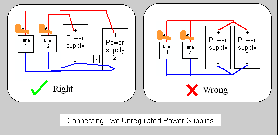
NOTE - The blue wire
"x" in the diagram is often necessary to get the lap recorders working
- the power supply to the cars will work properly if it omitted.
Chris Frost
Copyright © 2000
-2002 British Slot Car Racing Association updated
2004, 2005, 2009, 2022 All
rights reserved
No liability is accepted for
the information on this site or any use to which it may be put
